MICROFIBER-PAM
Probing of Cells and Tissue in Microbial Mats and Leaves
Features
The MICROFIBER-PAM employs thin (100 µm) optical fibers for fluorescence excitation and detection. The thin fiber allows probing of small spots of heterogeneous photosynthetic surfaces like soil crusts.
A “working fiber” (MF-F, accessory), which is inserted into a leaf or a photosynthetic mat, measures photosynthetic gradients inside the sample. For easier penetration, the working fiber can be pulled out to a tapered tip of 10 to 30 μm.

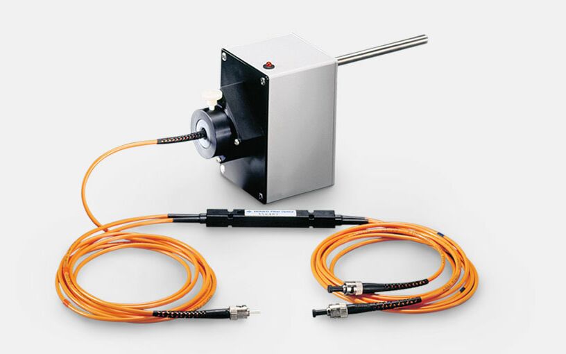
Fiber optic coupler consisting of a central beam splitter (black elongated central part) and four multi-mode optical fibers (orange lines) with ST (straight tip) connectors. Grey box: Photomultiplier.
Outstanding Properties of the MICROFIBER-PAM
- PAM fluorometer with the thinnest fiberoptics cable
- Ultrahigh sensitivity
- Four measuring light colors available
- Measurement of light attenuation
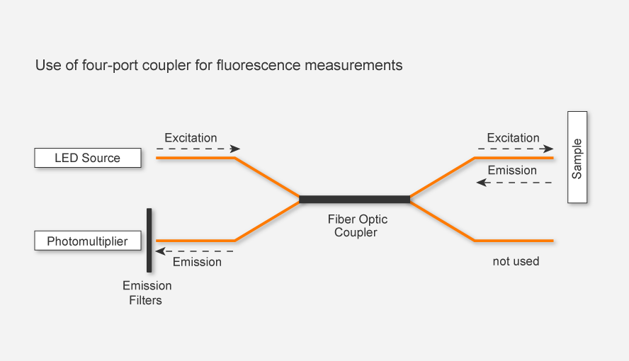
The fiberoptics system of the MICROFIBER-PAM consists of two pairs of optical fibers. A fiberoptics coupler optically connects the fibers. Two fibers link the light source and the photomultiplier, respectively, to one end of the fiberoptics coupler. The two other fibers link the sample to the opposite end of the fiberoptics coupler.
For fluorescence measurements, the fiber optic coupler guides light from the LED via a single fiber to the sample, and it transmits the fluorescence emitted by the sample to the photomultiplier. Color filters prevent LED light from reaching the photomultiplier. To measure light attenuation, the two sample fibers are placed at opposite sides of the object of study and color filters are removed (see Figs. 1 and 2 below).
Fluorescence excitation and detection are controlled by the PAM-CONTROL unit, which allows stand-alone operation of the MICROFIBER-PAM but also functions as an interface for operation of the system by a Windows computer.
The PAM-CONTROL unit can be operated by the WinControl software versions 2 or 3. The system includes, an RS-232 cable, a USB-RS-232 adapter (when an RS-232 port is not available), a charger MINI-PAM/L, a cable to connect a chart recorder, a transport box, and a stand (ST-101).
Functional Diagram MICROFIBER-PAM
Fluorescence measurement (Fig. 1): Blue light passes through a short-pass filter transmitting light only at wavelengths smaller than 600 nm (MF-L470). A fiber guides the LED light to the four-port fiberoptic coupler, MF-2-2-100. Another fiber directs the LED light from there to the sample, and guides fluorescence back to the fiberoptic coupler. LED light and fluorescence are then transmitted fiberoptically to the photomultiplier (PM-MF).
Only fluorescence light reaches the photomultiplier because it is protected against the blue LED light by long-pass filters transmitting light only at wavelength longer than 640 nm. The fiber adapter for the photomultiplier is part of the MICROFIBER-PAM adapter set, MF-A. The MF-A adapter set also includes a holder for the blue LED and three additional LEDs.
Light attenuation measurement (Fig. 2): Without the color filters in front of the LED and the photomultiplier, and with face-to-face orientation of the tips of the two sample fibers, the MICROFIBER-PAM detects the blue measuring light transmitted by the fiberoptics system to the photomultiplier. A sample placed between the fiber tips reduces the blue light intensity reaching the photomultiplier. The degree of light attenuation by a sample can be derived from the photomultiplier signal.

Figure 1: Outline of setup for fluorescence measurements. Measuring and actinic light from the LED is guided via the fiber optic coupler and the sample. Sample fluorescence is guided via the fiber optic coupler to the photomultiplier which is protected against LED light by a special filter set.
Get a quote
